It was hard, but the schematic is finally finished! Now I have to route the PCB, with a total of 722 components…
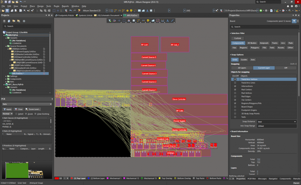
Still a lot of work to do, let’s see if I can finish it and get the PCB ordered before my holidays to assemble it then!

Pushing the DIY projects to the limit
It was hard, but the schematic is finally finished! Now I have to route the PCB, with a total of 722 components…
Still a lot of work to do, let’s see if I can finish it and get the PCB ordered before my holidays to assemble it then!
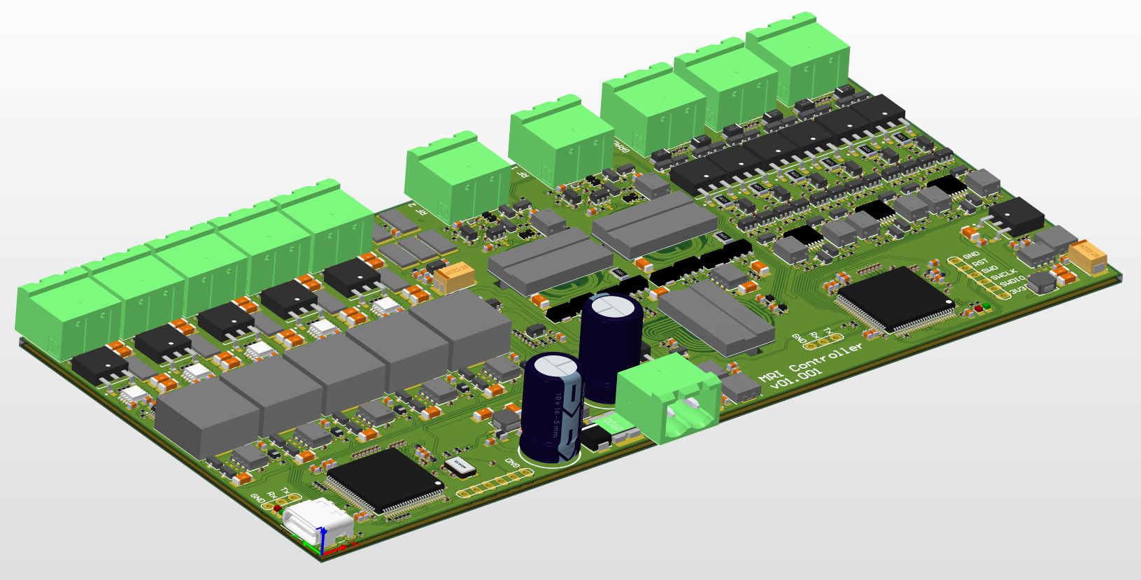
It took me about 2 weeks of work in my free time, but the PCB is finally finished! The main features:
Two microcontrollers are used (STM32H7 family). The master is used to communicate with the computer through USB (USB 2.0 over a USB C connector) and to send commands to the slave. It also controls the PWMs of the 5 drivers to generate the B0 magnetic field, and to control each linear current source using each DAC (through SPI). It also measures the temperature using a NTC, thermally coupled to all the shunt resistors, and compensates the current setpoint when the shunt resistors temperature changes according to the temperature coefficient of each resistor, which was chosen as low as possible (100ppm/ºC).
The slave microcontroller is the one that performs the main MRI tasks. It generates both RF signals (the main and the 90º shifted one) using both internal DACs + DMA. It also controls the gradient magnetic field timings, and the integrated 16-bit ADC @ more than 5MSPS is used to capture the 210kHz signal.
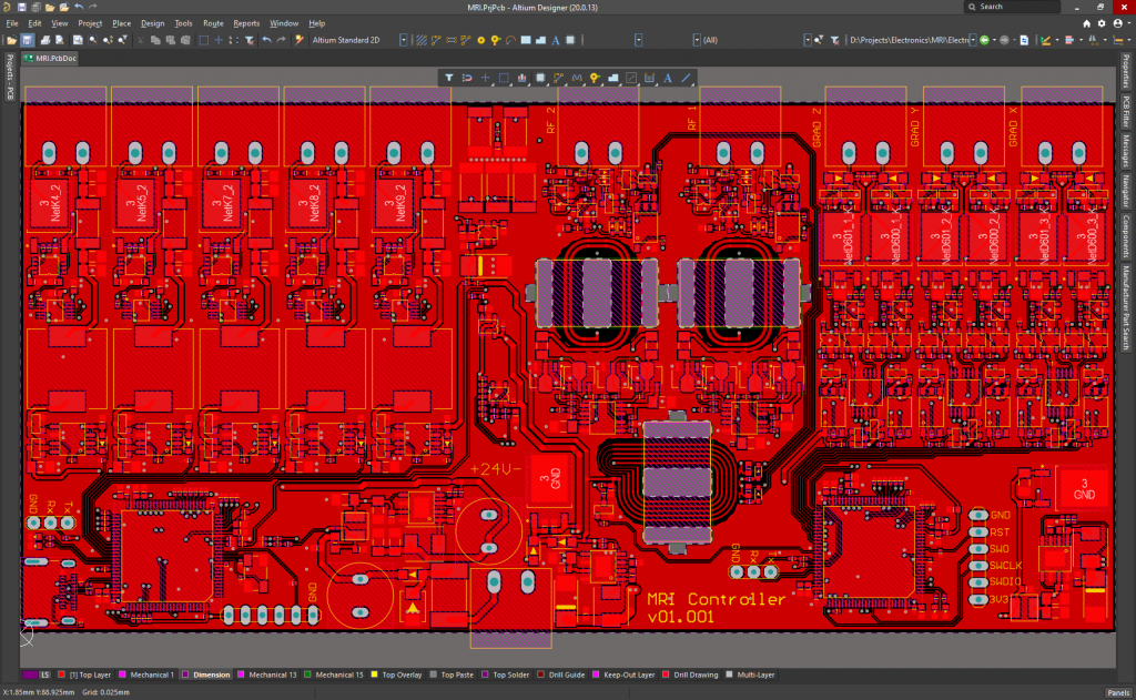
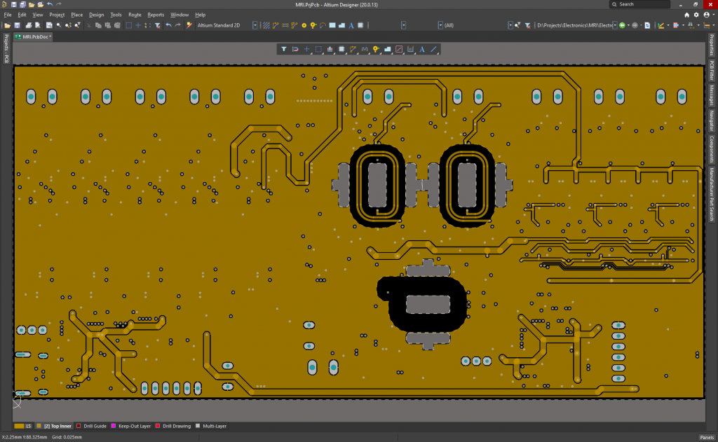
PCB Layers:
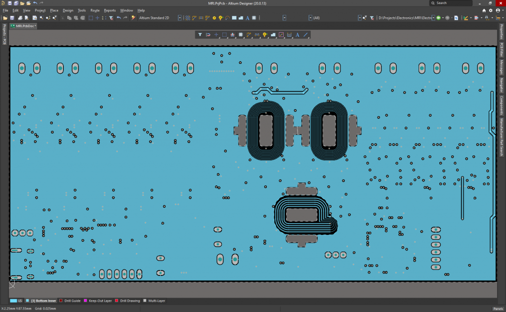

It is powered at 24V, although the microcontrollers can run and be programmed using the 5V of the USB C connector when plugged to the PC. It measures 165.2mmx80mm, and it has been ordered to Eurocircuits today.
I will assemble it next week, I’ll post the results soon!